School Projects
Educational lecture props
While studying at Sierra college, I noticed that the math professors lacked any fun physical props to demonstrate some of the complex topics that they needed to present in lecture, so I set out to make some for the department. I designed and fabricated three projects
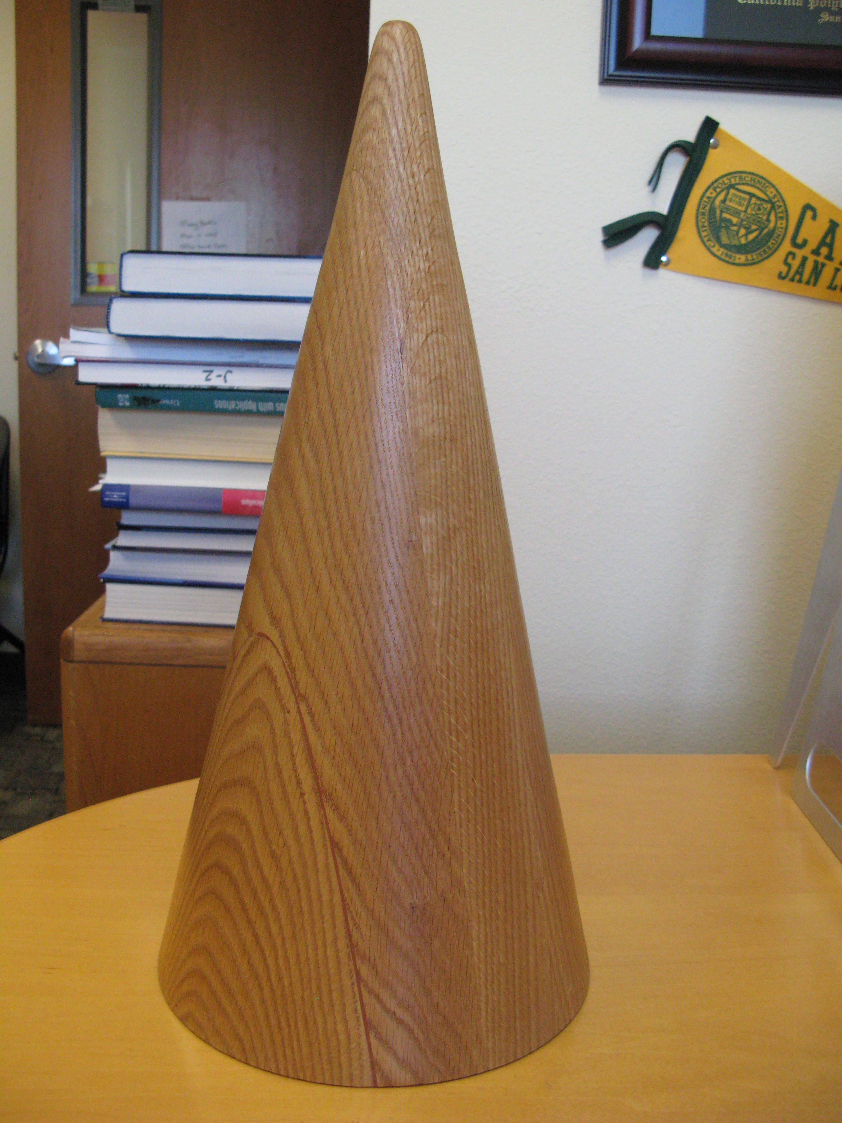
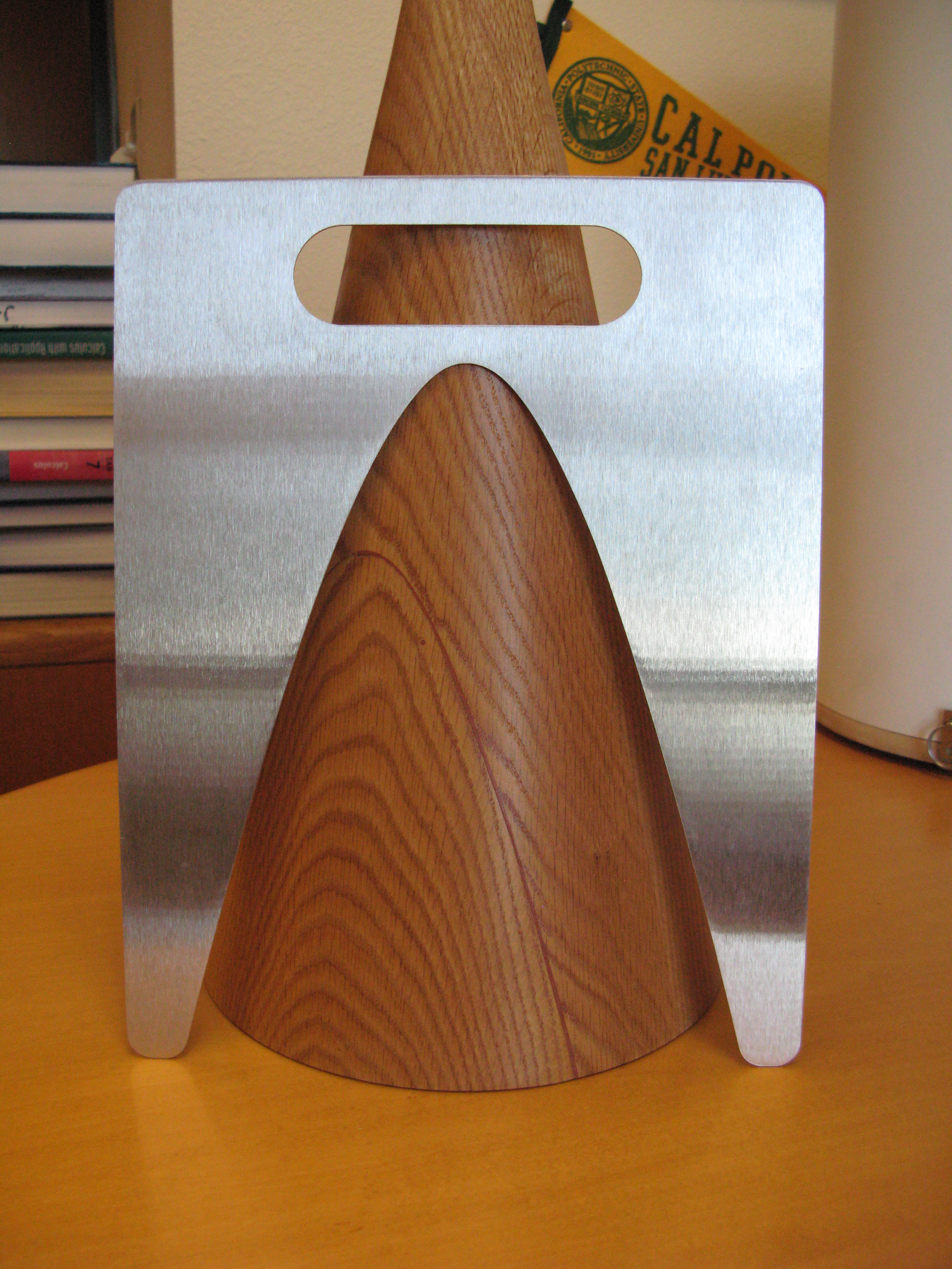
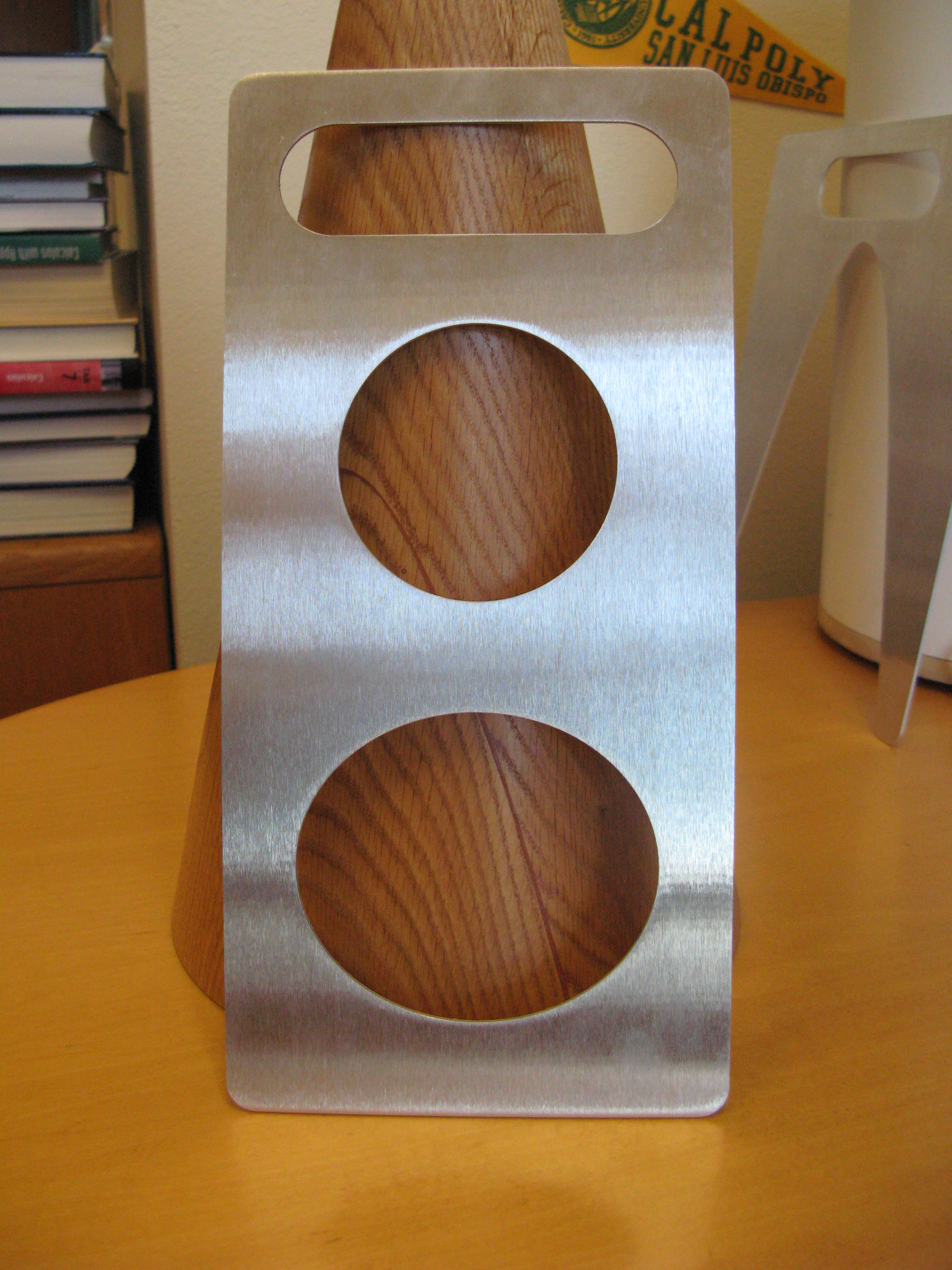
1.) A classic Apollonius cone made from red oak wood complete with sheet metal templates to show the standard conic sections and a carrying case.
2.) A hyperbolic paraboloid with powder coated vectors demonstrating local curvature directions formed using a home made vacuum table.
3.) A model made from acrylic demonstrating the logic of spherical coordinates by associating them with a literal ball for the student to hold.
SMUD solar boat regatta
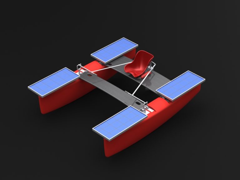
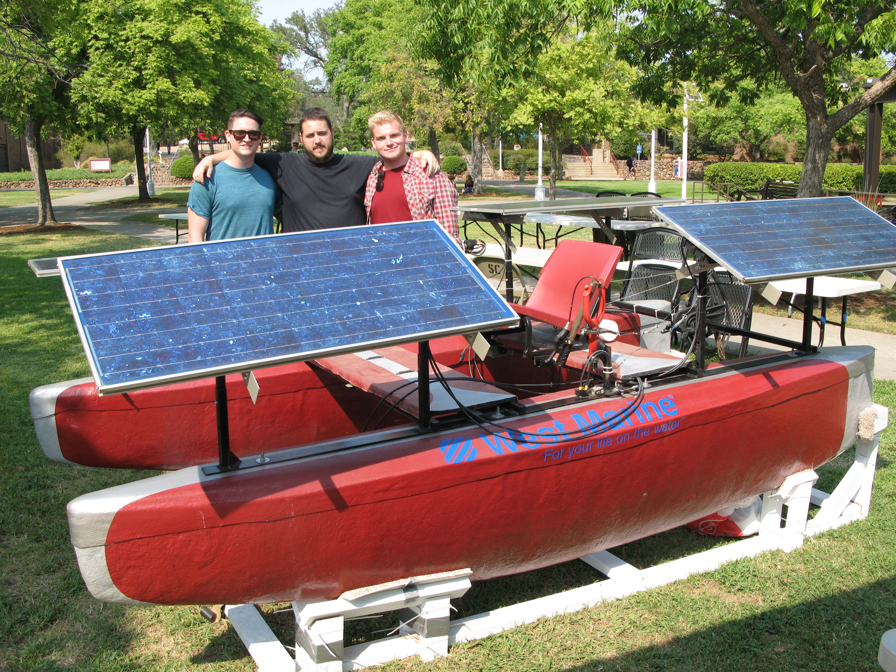
In 2013, the engineering team at Sierra college participated in a solar boat design competition. The event was held as a regatta; with events for maneuverability, speed and power consumption. Our team was the only one to build our hulls from scratch out of fiberglass, which meant that we had also built the molds by hand. In addition to working with the hull team on the mold design, construction, and layout I functioned as the lead designer for the team, producing all the computer models used in the layout.
Cerynitis 1
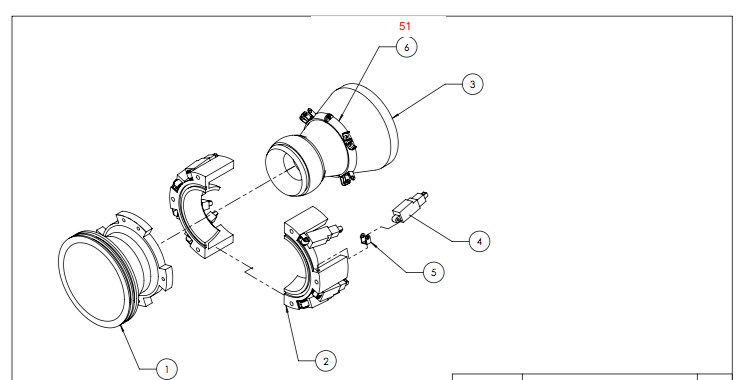
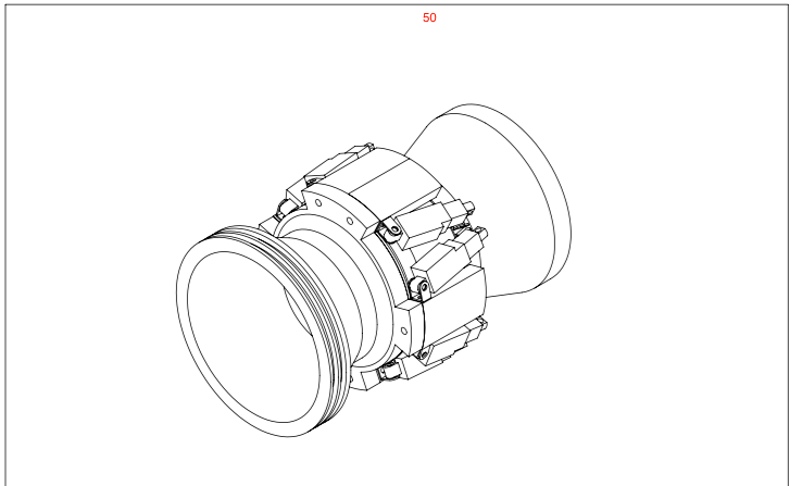
Alex Engler, an aeronautical engineering student at Cal Poly Pomona brought me in to assist with his design for a self correcting rocket. The core of his mechanism relied on a gimble being driven by computer controlled linear actuators responding to real time sensor data. Alex asked me to model his rocket for both fabrication and presentation purposes. I was able to design a fully articulated gimble using simplified geometry and minimal off the shelf parts for assembly. In addition, Alex requested that I design and fabricate a horizontally mounted testing platform where he could live fire the rocket and collect experimental data, which I welded together using standard square tube stock.
3D printed air compressor
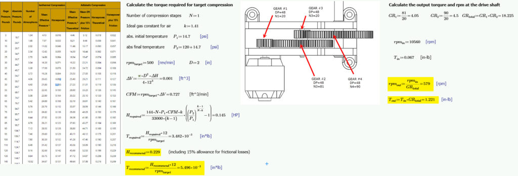
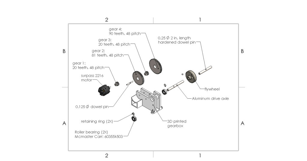
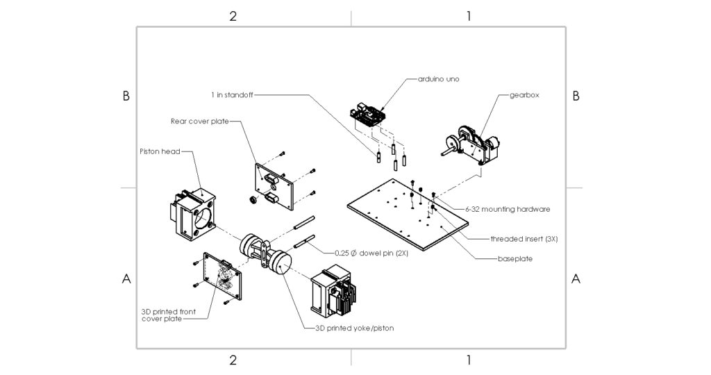
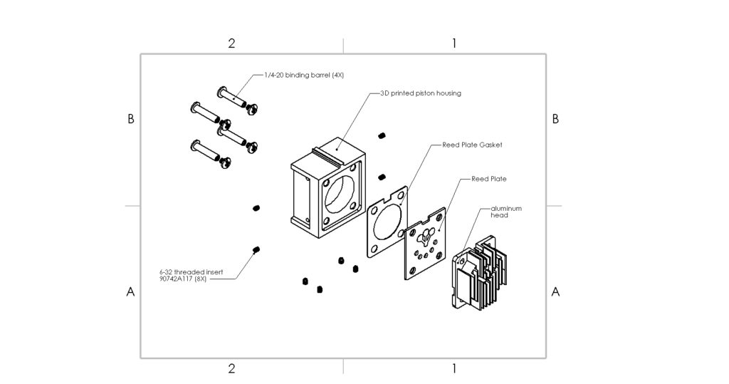
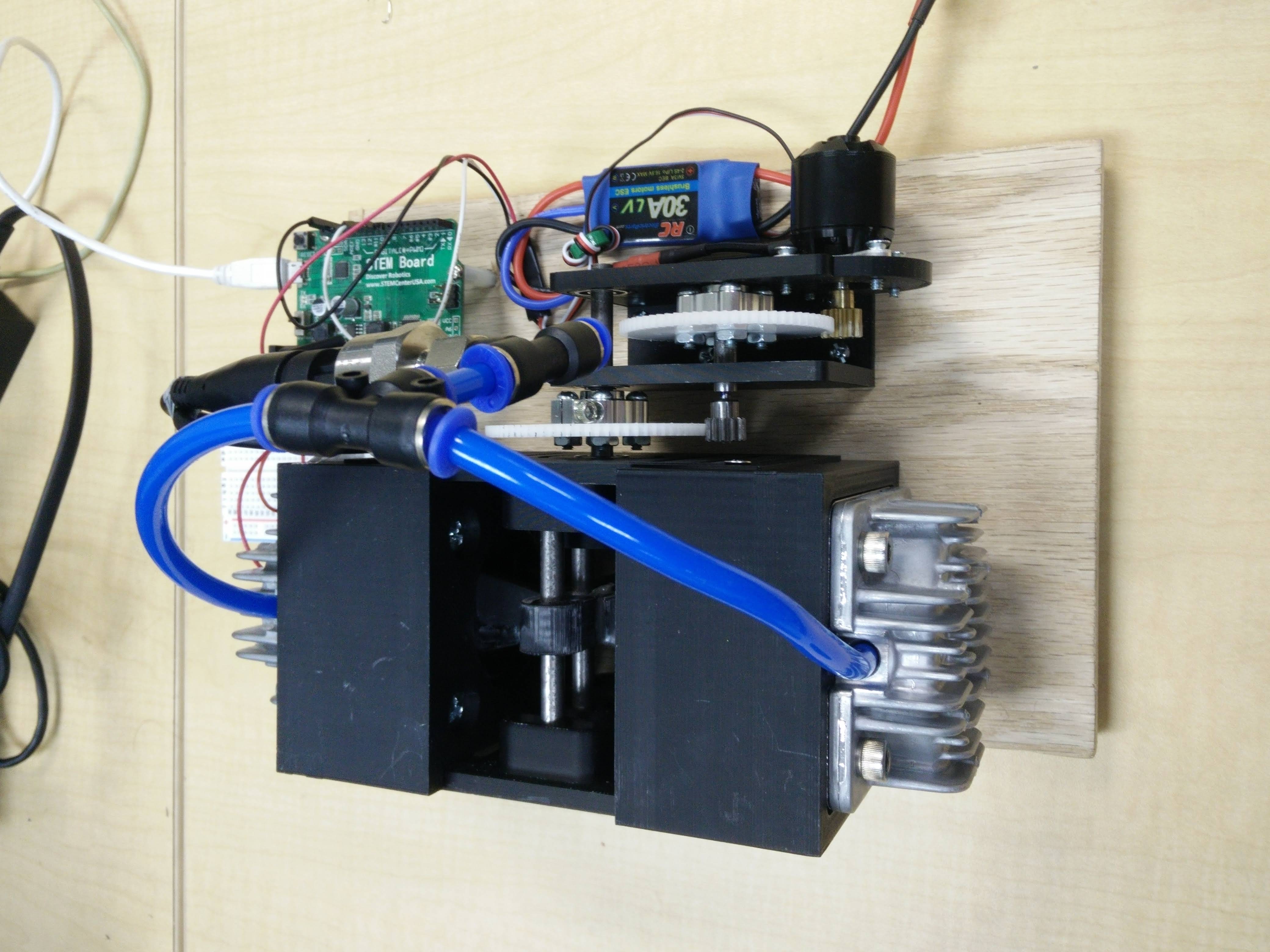
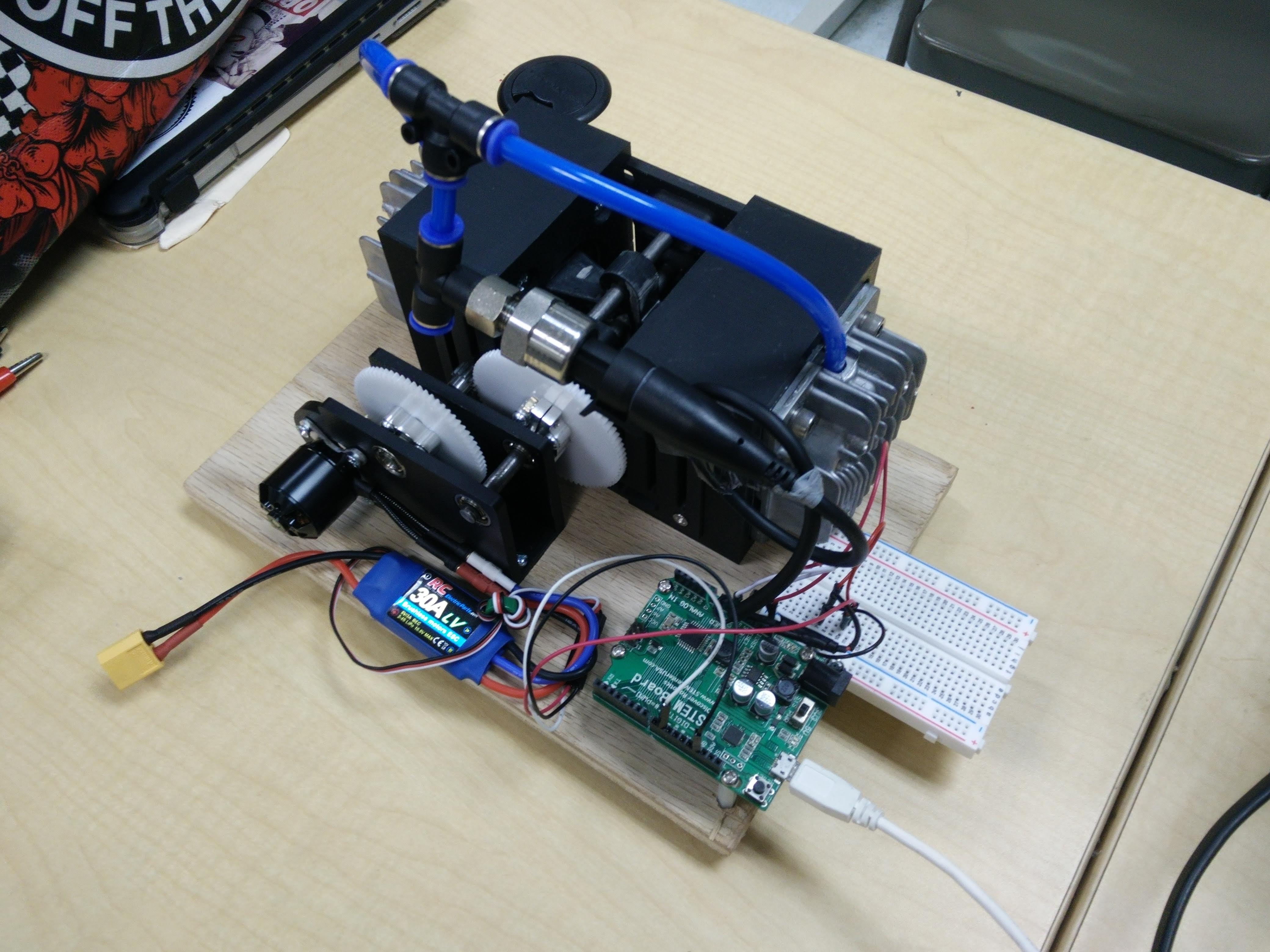
The goal of this project was to make a working air compressor using a majority of 3D printed parts that could sustain 100 psi for a minimum of 5 minutes. As the primary design lead on this project I elected to use a scotch yoke mechanism in order to take advantage of two cylinders providing more consistent air compression. The most significant challenge of this project involved balancing the required torque of the gearbox against the material strength of the printed plastic. In order to keep part weight to a minimum, careful attention was paid to part geometry using ribs for profile reinforcement normal to the direction of loading.
Prosthetic thumb
In the fall of 2019, civil engineering student at Cal Poly Pomona Daniel Castillo lost his left thumb while working on a concrete canoe project. I approached Daniel and told him about a friend of mine studying bio medical engineering at Cal Poly San Luis Obispo. Together, we proposed doing the first known inter-university project between the sister schools in order to design and build Daniel a new prosthetic thumb. My team role was to act as the patient liason; collecting data on his hand functionality in order to establish the operating constraints of the prosthetic, taking castings and 3D scans of the damaged area, as well as modeling the final housing components for printing. The project was a success, and Daniel reported that this prosthetic design was the most comfortable version he owned compared to professional models made by firms like Naked Prosthetics. The project also attracted attention from the student newspaper at Cal Poly San Luis Obispo, and came in 2nd place at the end of the year for overall outstanding student work at Cal Poly Pomona.
Product Design
Food processing pump carts
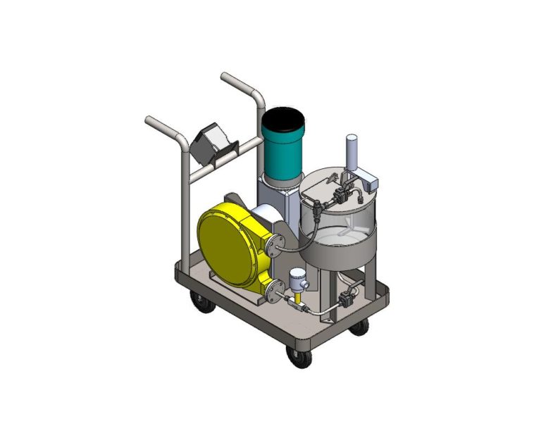
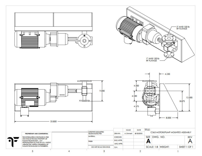
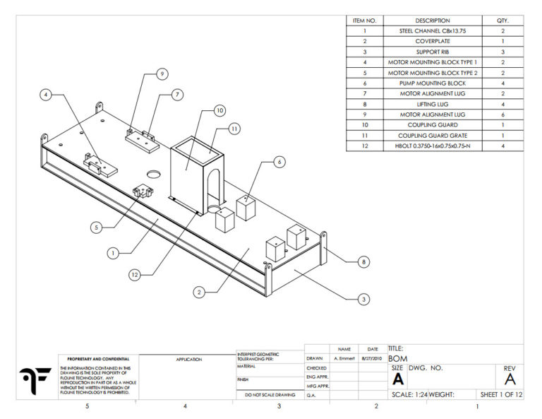
As a consulting draftsman for Flo-Line Technologies, I helped bridge the knowledge gap of their senior application engineers from 2D information to 3D models that were more client friendly. Flo-Line specializes in mobile pump carts that are used in the food processing industries and my primary responsibility was laying out how that cart would be assembled and detailing fabrication prints. This meant that I needed to be considerate of where secondary systems serving the pump were installed in order to maintain easy accessibility and intuitive operation for the end-user in tight operating environments.
The Pop-Mop
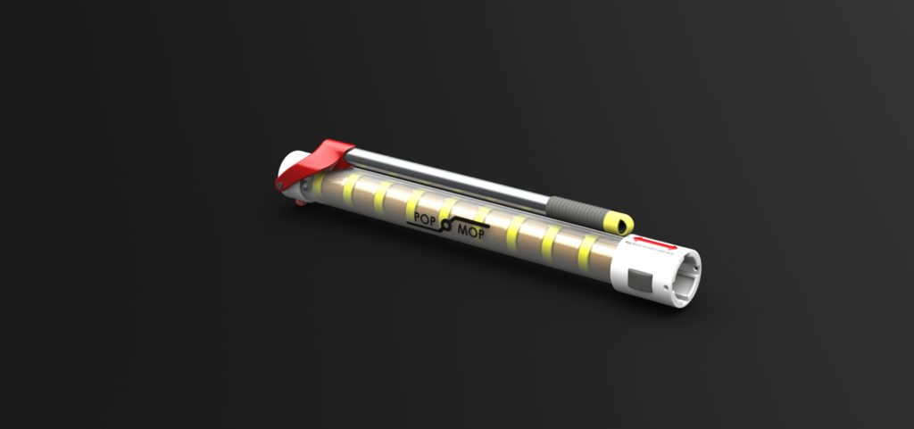
As a consultant for Dave Lampson servicing the private inventor community, I assisted first time inventors making the leap from concept to prototype by creating functional models using Solidworks, followed by basic fabrication or education to our client base on how to build up their own fabrication skills. This project was a design intended for the airline industry, a mini-sized mop that could be packed down into a space no more than 18 inches overall, but with a cartridge based head system that could store up to 5 self contained, single-use, mop heads. Such tight operating envelopes and the limitations of 3D printed prototype parts at the time necessitated a clever solution, which I was able to deliver. The final prototype used a simple collet to eject used mop heads while allowing a fresh cartridge to be fed into the nozzle. The handle was collapsible and used a custom hinge mechanism that allowed for only open and closed positions in order to make sure the mop remained closed reliably while being stowed.
Safer lock
Joe Simpson, the founder of gatekeeper innovation, approached me for help designing a cap with an integrated combination lock for pharmaceutical bottles. Working with a local machinist named Charlie VanNoland, we were able to design and machine a prototype cap that was compatible with a wide range of the available prescription bottle styles. This compatibility proved to be one of the most challenging aspects of the project because the most common versions of prescription bottles do not use traditional threads to mount the cap. The other major challenge of the project was trying to figure out how to pack the required mechanism into a reasonably sized space. There were mixed results in the end on this second challenge, due to the constraints of the selected fabrication method and a focus on proof-of-concept rather than mass production focused design.

Triplicates
As a young designer, I understood very early on that engineers exist in a service role relative to the machinists, tool makers, welders, and operators that they support. I invested significant time and energy during these initial years into learning and working with whatever machines I could get access too in order to form a mental understanding of how these roles operate within the larger framework of the design and manufacturing process.
The board game shown here was a training project assigned to me by Charlie VanNoland, owner and operator of a local machine shop. I was tasked with the entire design process, submitting drawings for manufacture approval, and multiple design reviews where Charlie would explain to me the relative effectiveness of my decisions. Charlie then supervised as I selected and ordered raw stock material, wrote code and generated tool paths for the machines, cut parts and worked with outside coating vendors. The result of this effort was a game that was nearly optioned by Hasbro a few years later when presented at the annual toy and game convention in Chicago.
Killer Tools
Tim Gerhards, a private inventor specializing in automotive repair tools, often used me in order to polish and detail tool designs that were moving from the initial prototype phase to small scale manufacturing runs. Tim is a talented fabricator on his own and his projects, ranging from a pneumatic cylinder for bumper repairs to a sheet metal bracket that aids in wire soldering repairs were always a pleasure to work on.
Industrial Design
Machine shop work benches
While studying at Cal Poly Pomona, I worked full time in the on-campus machine shop in and out of semester. Among the many projects I did while trying to keep students safe included rebuilding an entire concrete lab for civil engineering students; layout, demolition and construction of new area installations in the shop to support student teams, as well as the design and fabrication of new workbenches and tool storage tables.
All the benches were designed using standard square tubing out of steel and then welded together before being mounted with a butcher block counter with polyurethane coating for durability. One of these tables, affectionately referred to as “Big Bertha” was 23’x8′ and supported 3/8″ steel counter top, designed specifically as a workspace for the student bridge design team.
Dynacast automated machine cells
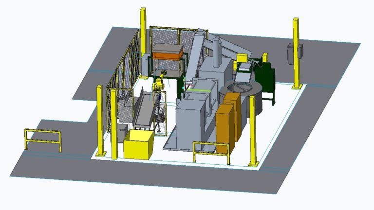
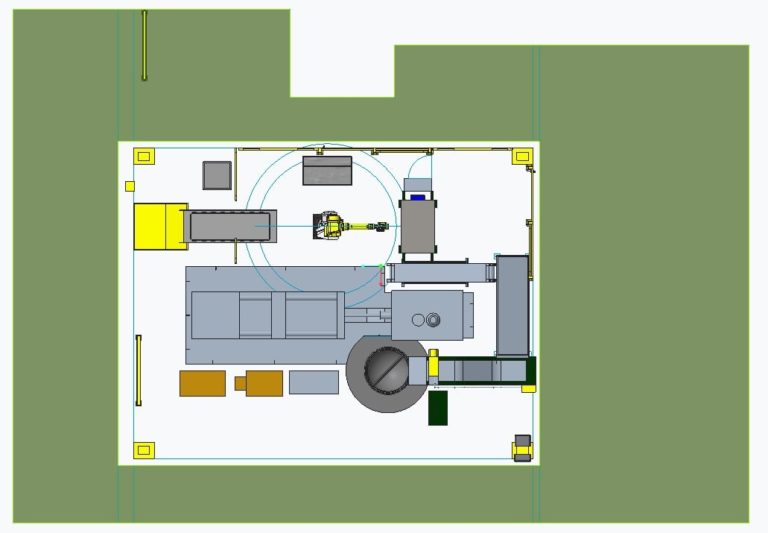
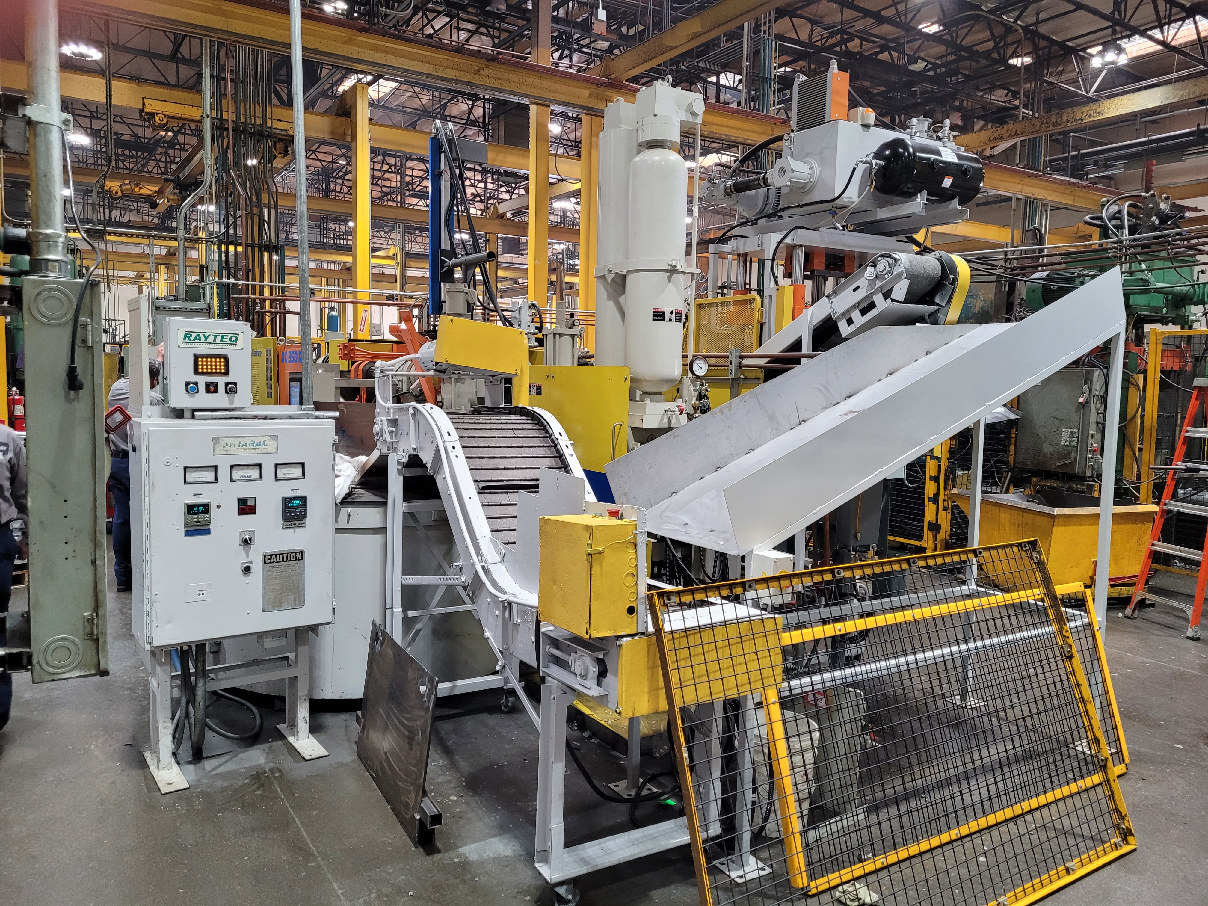
In the later half of 2020 the Dynacast factory located in Lake Forest California purchased a total of three new die casting machines from the Shibaura company with the goal of installing fully autonomous machine cells that could continuously produce up to 3 castings per minute. The installation of a die cast machine cell requires a full range of support equipment, including furnaces, vision systems, trim presses, robotic arms, and part catching robots. All of these machines work in concert together retrieve raw castings, process them, and deliver the remaining metal to the furnace for remelting. As a training engineer at Dynacast, I was specially selected to be the lead designer laying out the orientation and plan to install all these components into the finished arrangement. This project was large in scope and plagued with problems such as; budgetary restrictions, incorrect machine configurations, and vendor communication breakdowns. Despite all of the significant hurdles placed in front of me, I quickly developed and executed creative solutions to accommodate emerging problems on a daily basis in an environment in which the constraints and considerations are constantly changing.
Few other engineers can be dropped into such an environment with minimal experience and be expected to survive, let alone thrive.
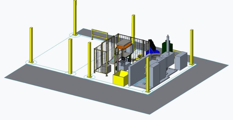
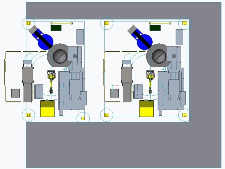
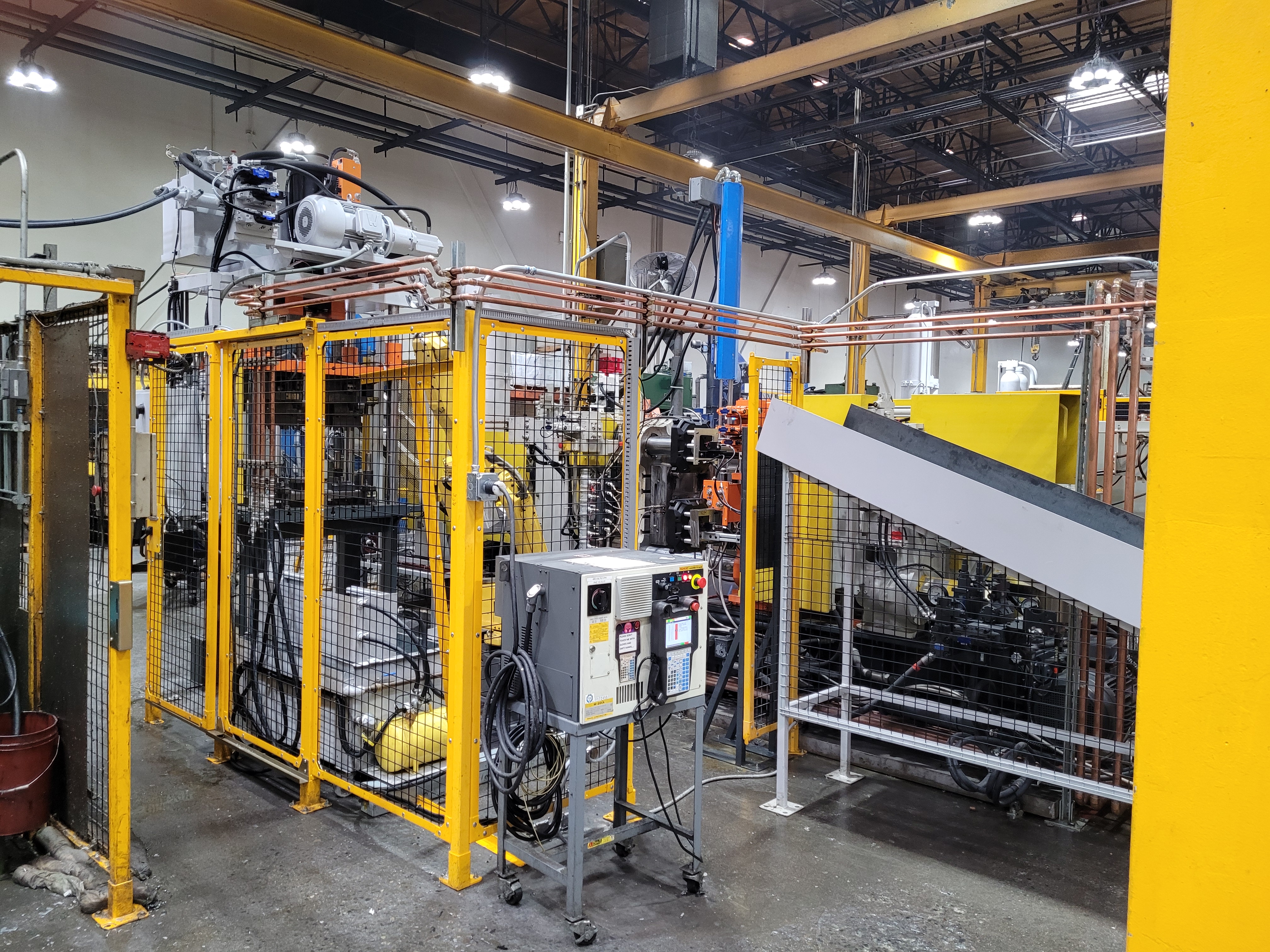
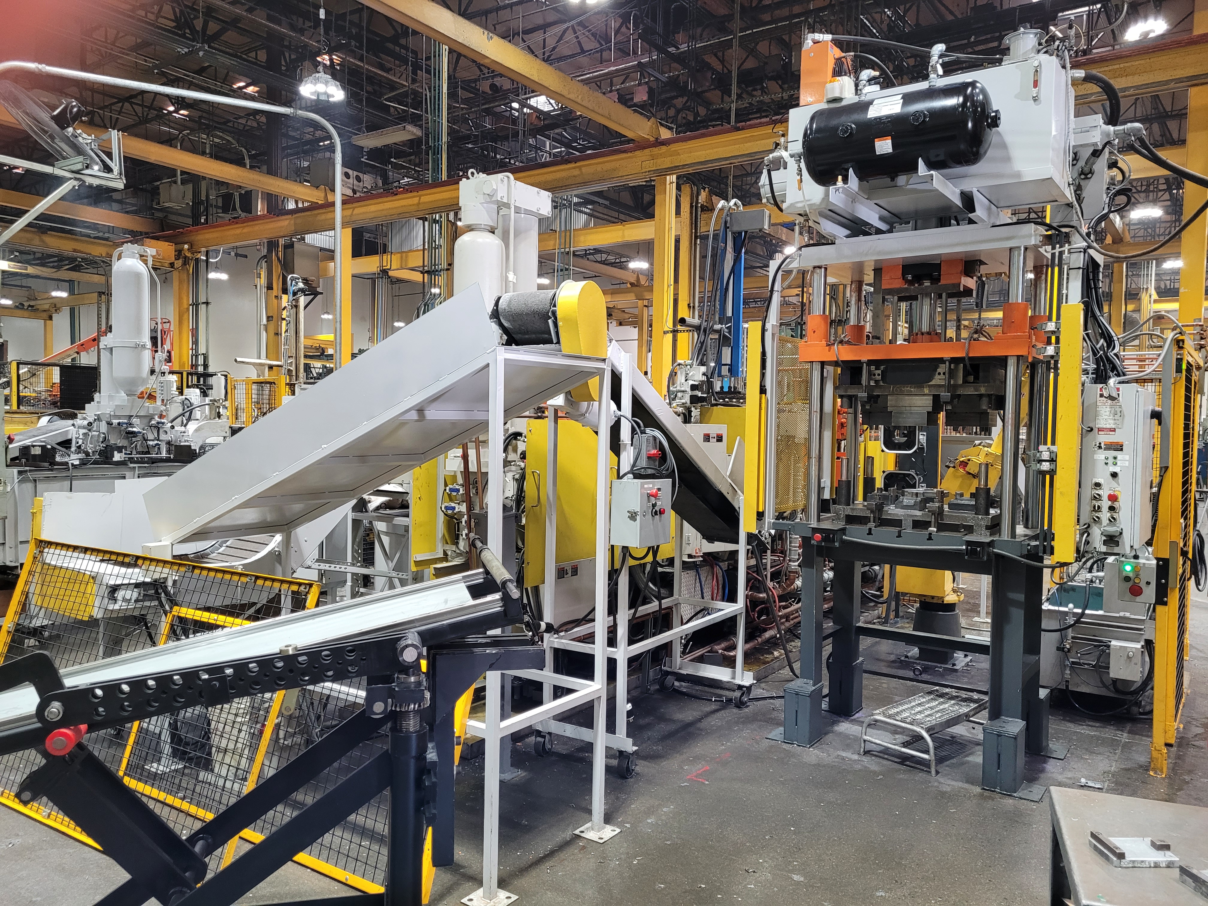
Dynacast automated part loading tray
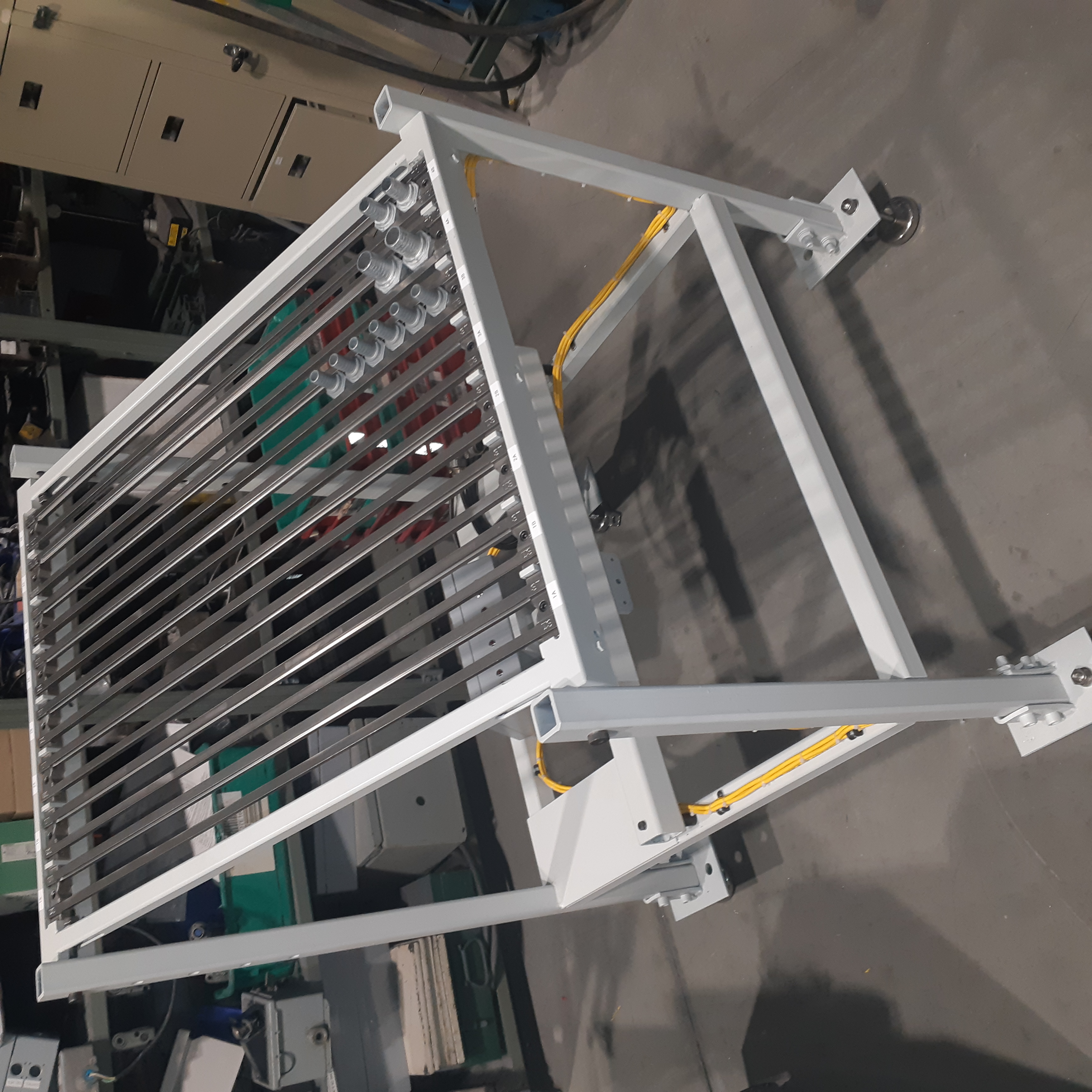
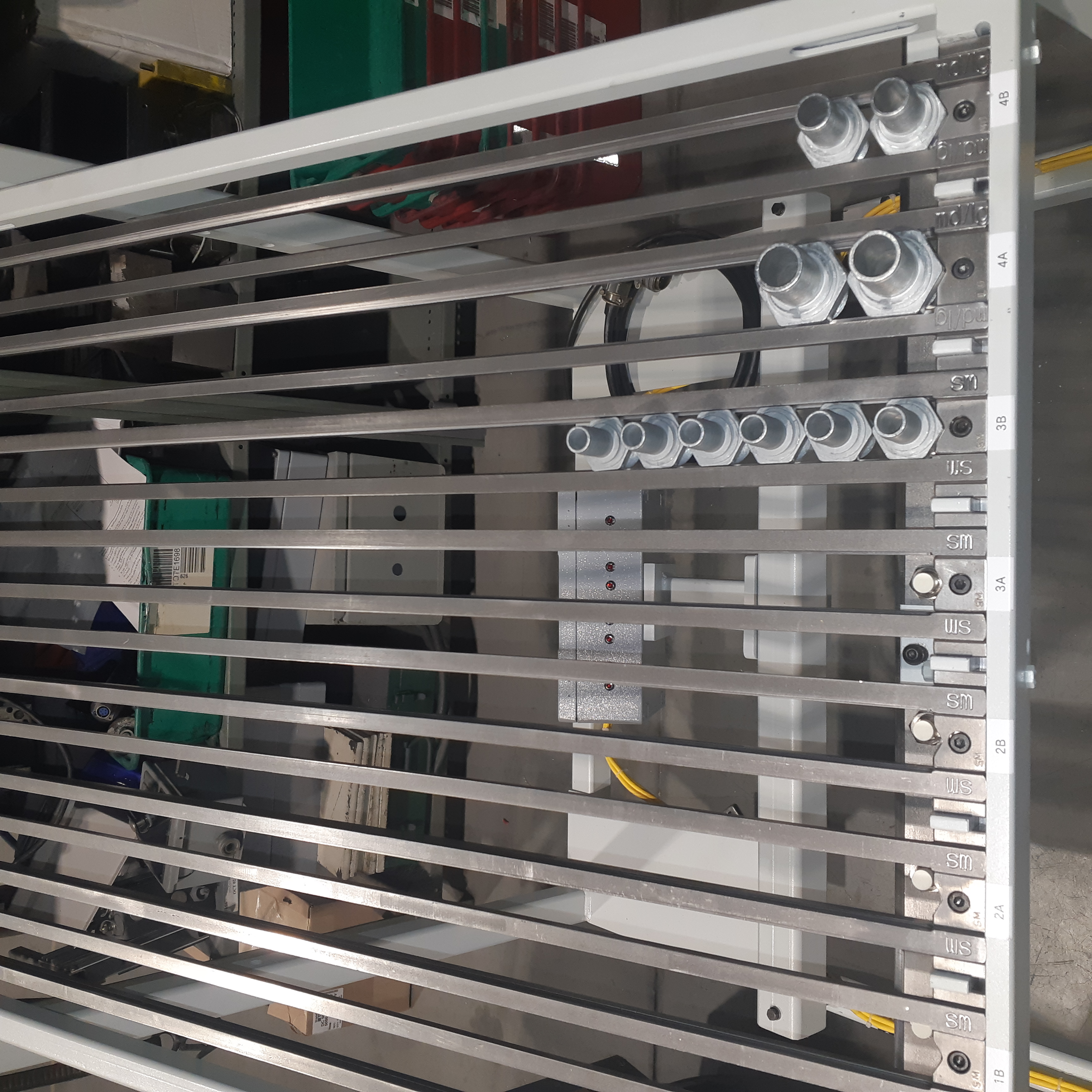
While training with the tooling design division in Wisconsin, I was specially selected to design a part delivery system that was intended to be installed in a partially automated machine cell. This frame, which was meant to be free standing and accommodate gas stem parts in three different sizes, would also have an adjustable incline and spacing that was purposefully sized to work with a dual headed robot gripper. The parts varied in size just enough that no one set of rail positions would work for all three parts simultaneously. Part of the challenge of this project was the struggle against current designer understanding and methodology at Dynacast, compared to my own understanding about what is and what is not acceptable to ask a fabricator to make.
Despite the resistance, I was able to provide a cost effective solution that allowed for acceptably fast reconfiguration with minimal required tools and design details that minimized the potential for user error. Now deployed at the Canadian Dynacast facility in Peterborough, this simple piece of automation hardware was built and installed without my receiving a single clarification request.

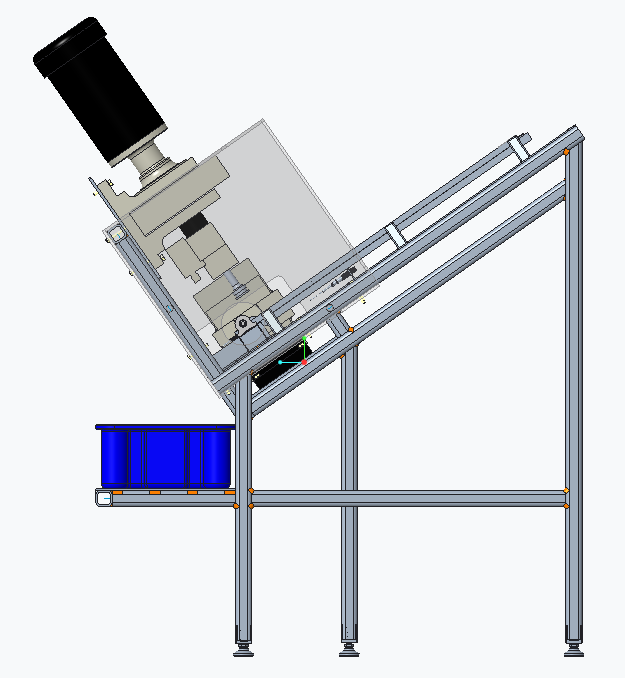
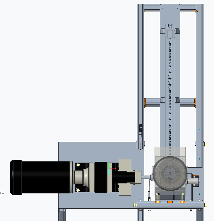
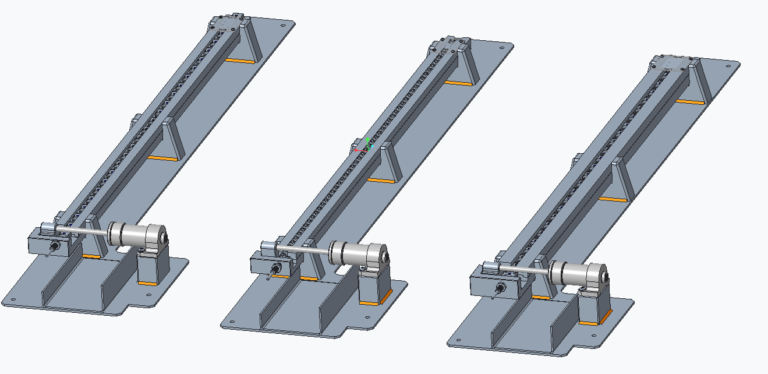
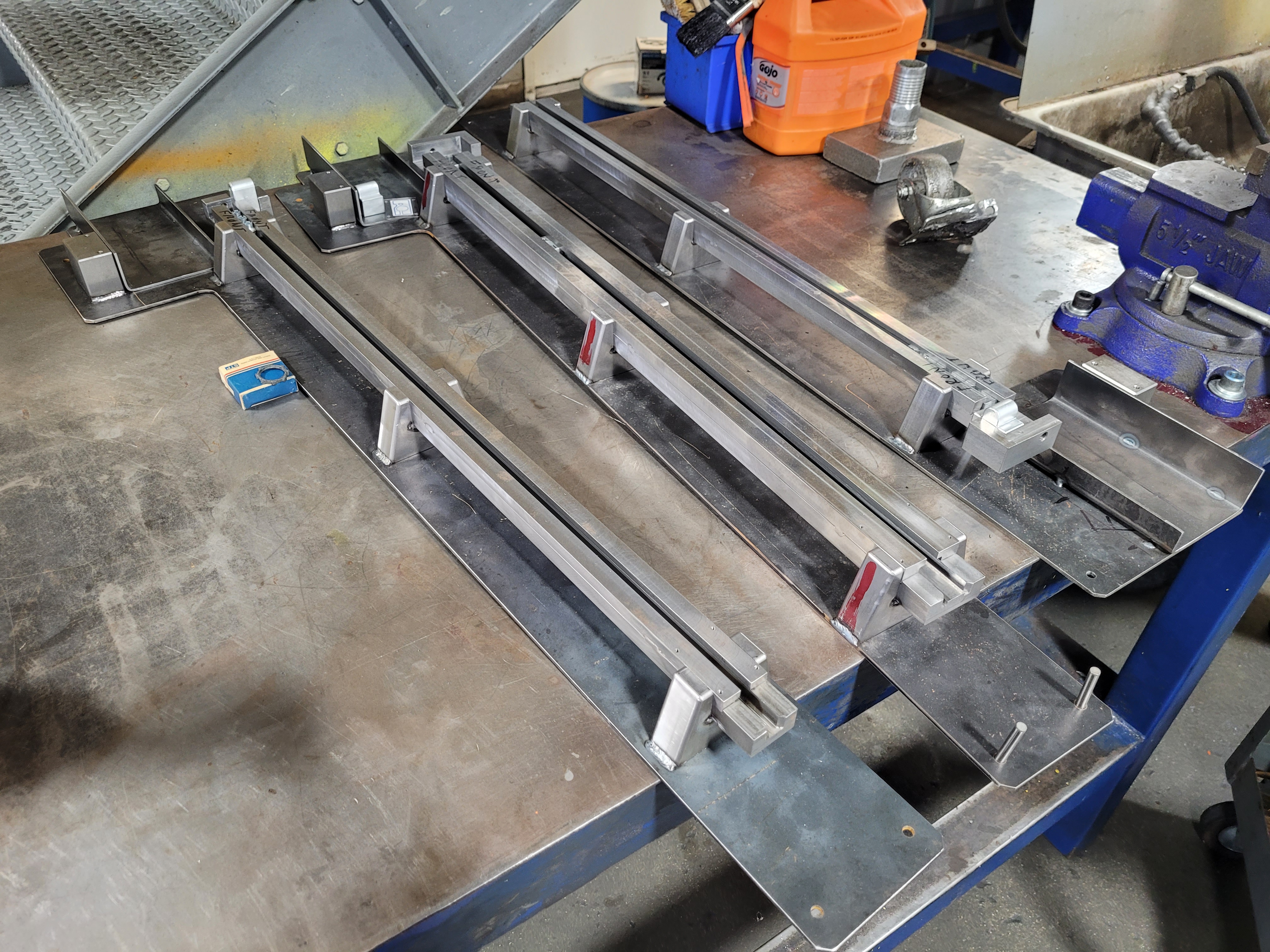
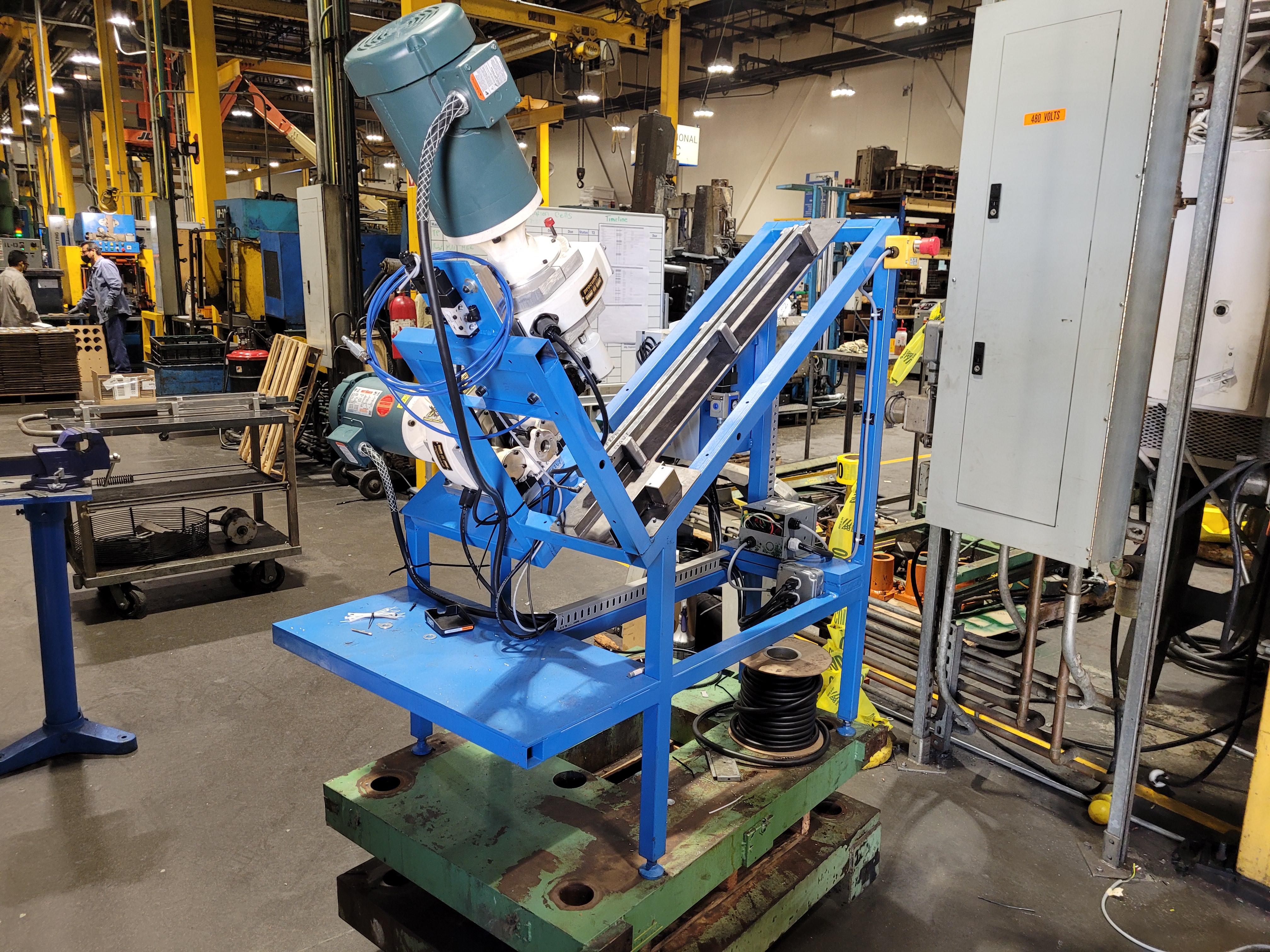
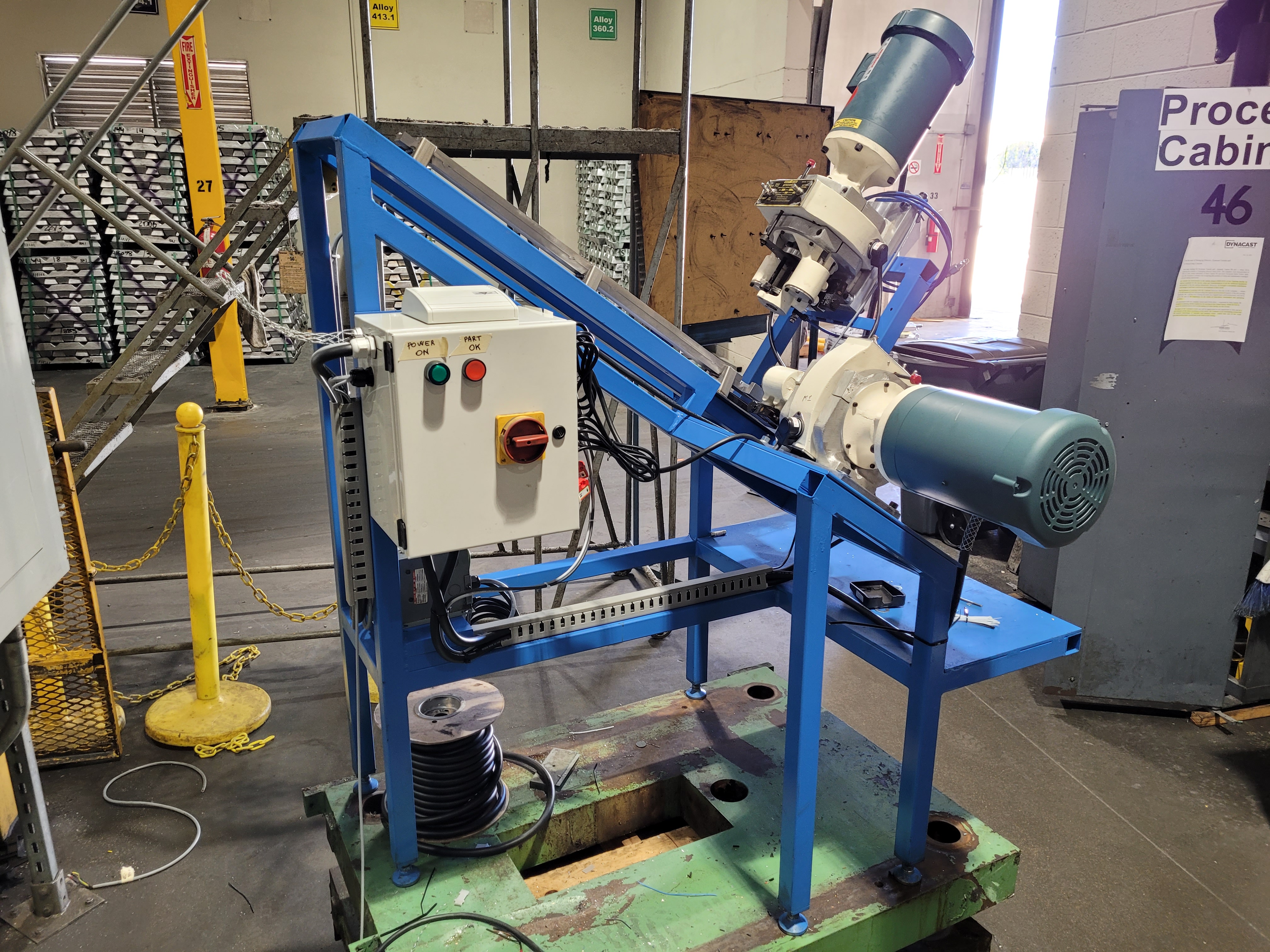
Dynacast automated part tapping machine
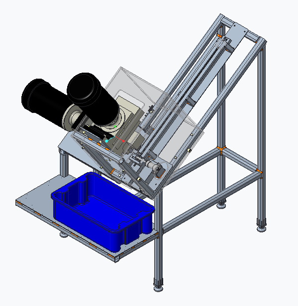
After the formal casting process, there is often a stage of post processing that must be done to most cast parts in order to create features like threaded holes. Such was the case for three different parts at Dynacast that all contained two perpendicular holes that required tapping. Once again I was specially selected to design a free standing mechanism that would mount two standard tapping heads, automatically positioning an array of cast parts for the tapping process, and then ejecting them for collection. I was to accomplish all of this with a design that included nearly impenetrable safety shielding and access to only a single welder in our maintenance department. I designed and supervised construction of a frame built out of stock steel tubing and developed a set of custom rails that ensured that the tapping heads themselves would never need to be adjusted.between parts. In order to change over tooling to tap any one of the three parts this machine accepts, all the operator has to do is swap out the entire rail assembly, which requires no tools. The biggest challenge of this project was relying on precise relative placement of critical parts to a tolerance of +/- 0.0005 inches that was dependent on a frame that was built in house with a tolerance of +/- 0.0625 with warped sections of tube. But despite all the hurdles and difficulties placed in front of me, I found a way through to the end.
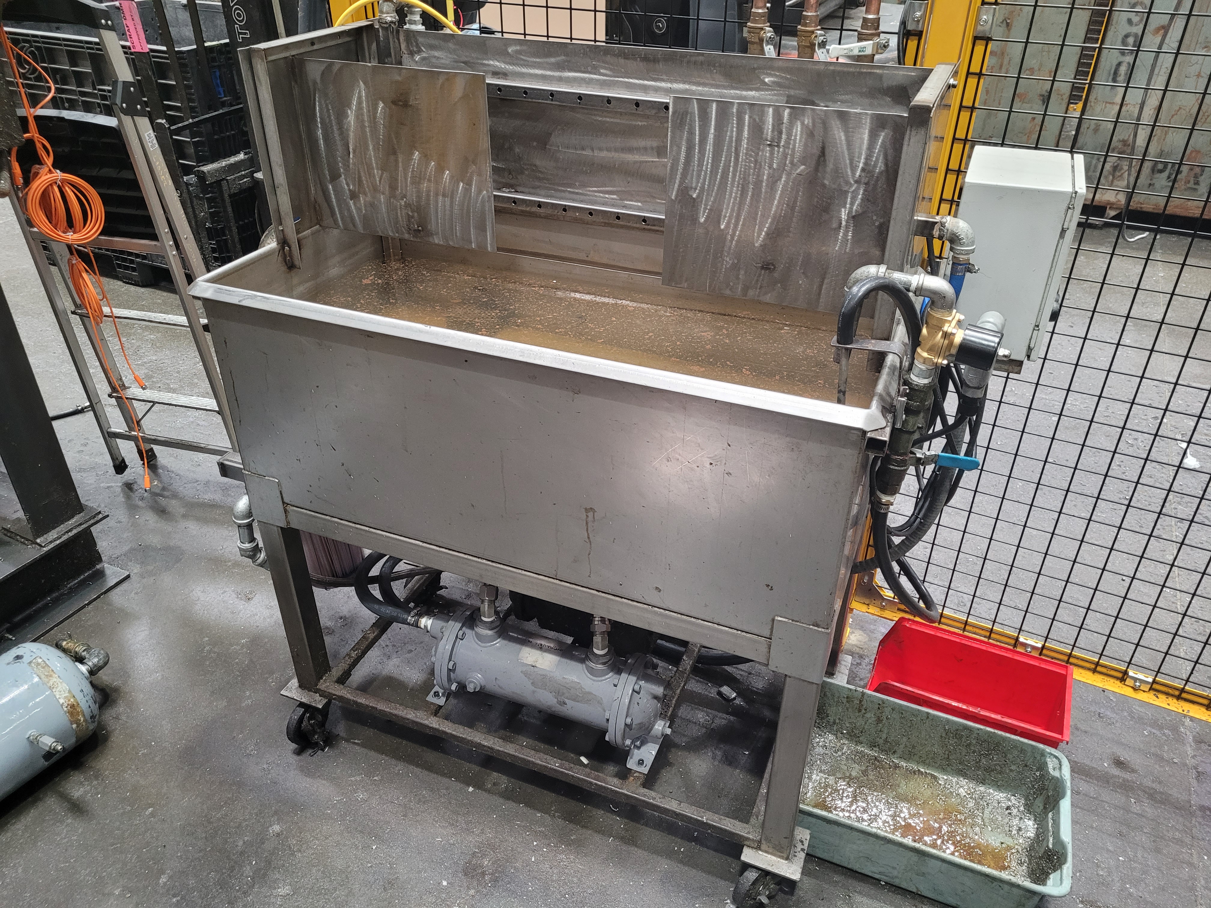
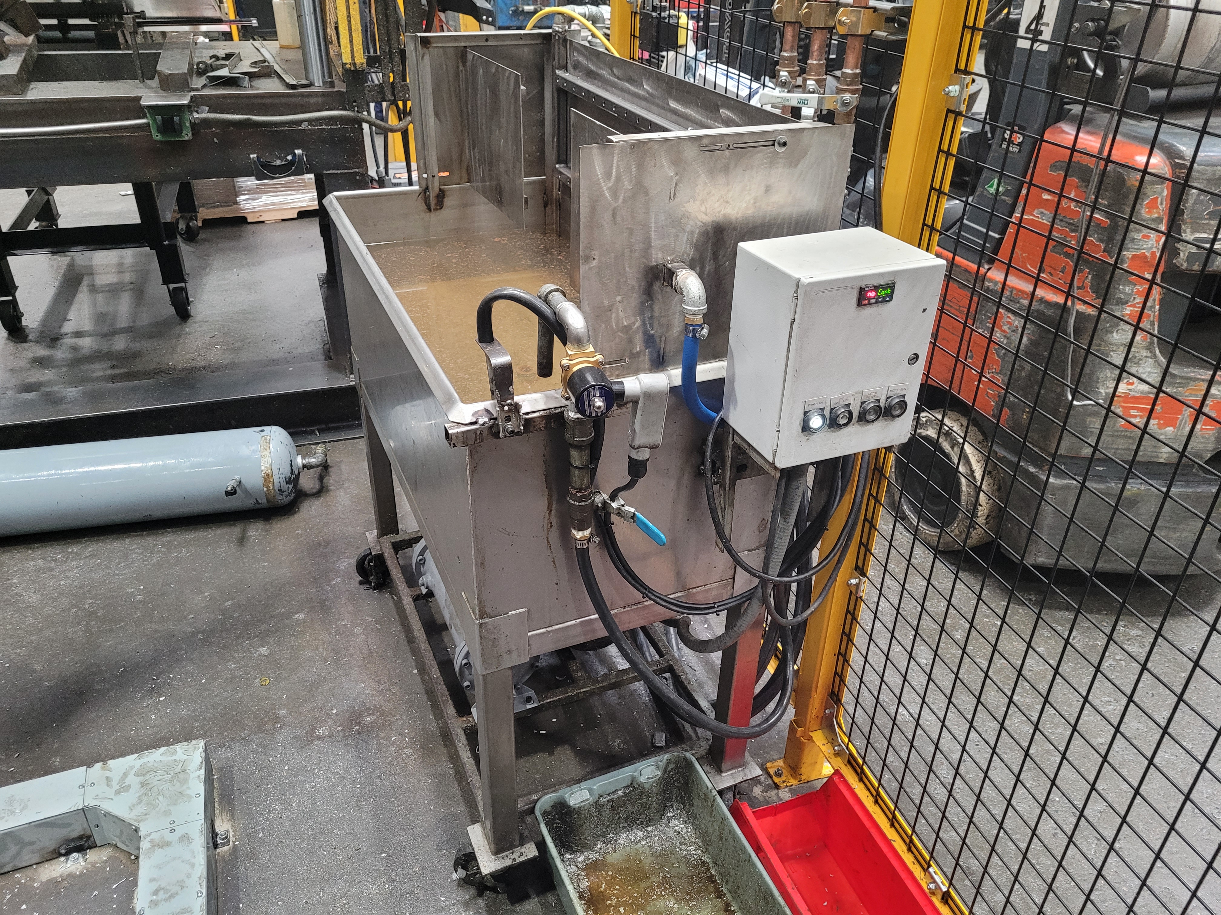
Dynacast low cost quench tank
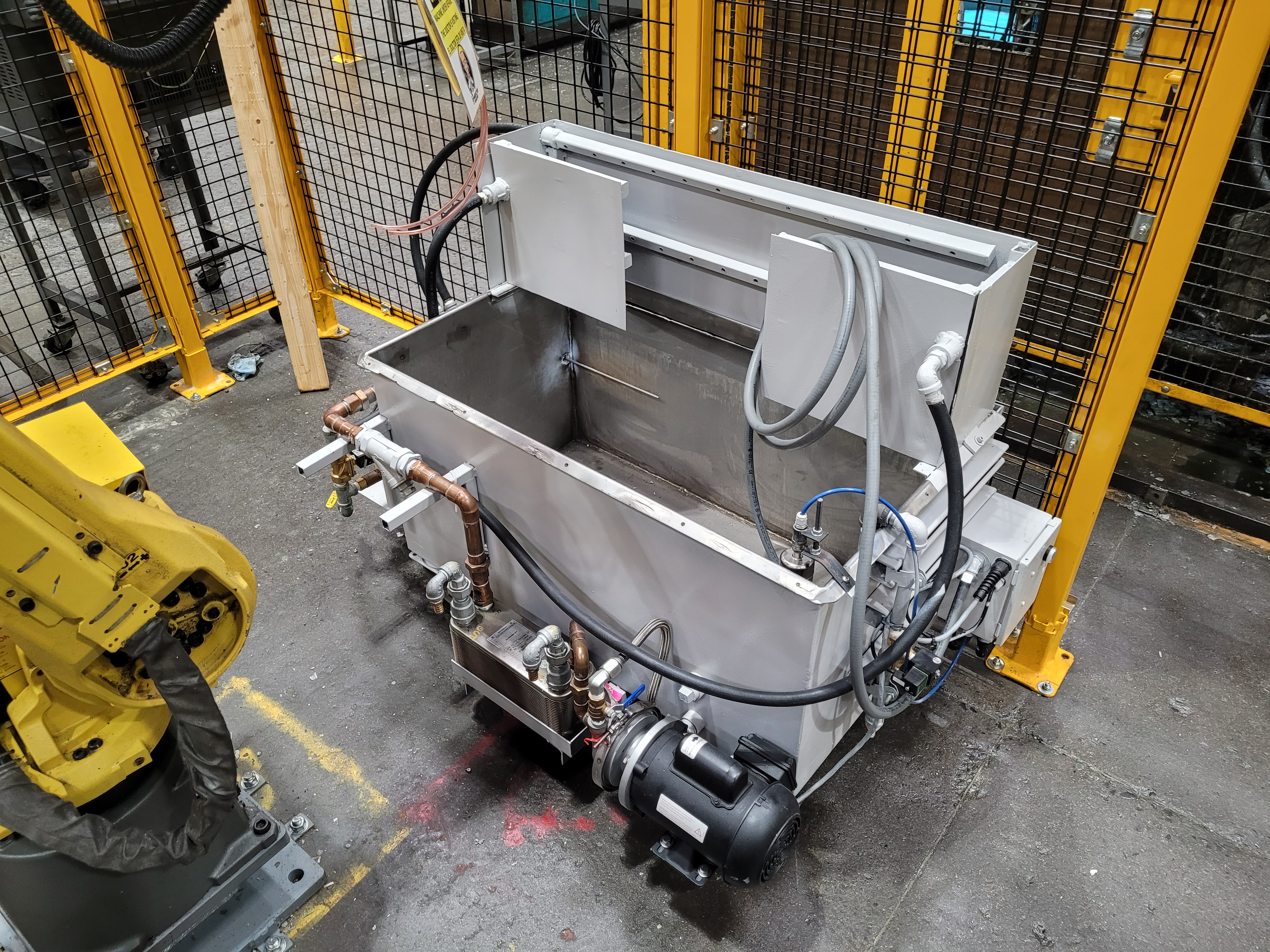
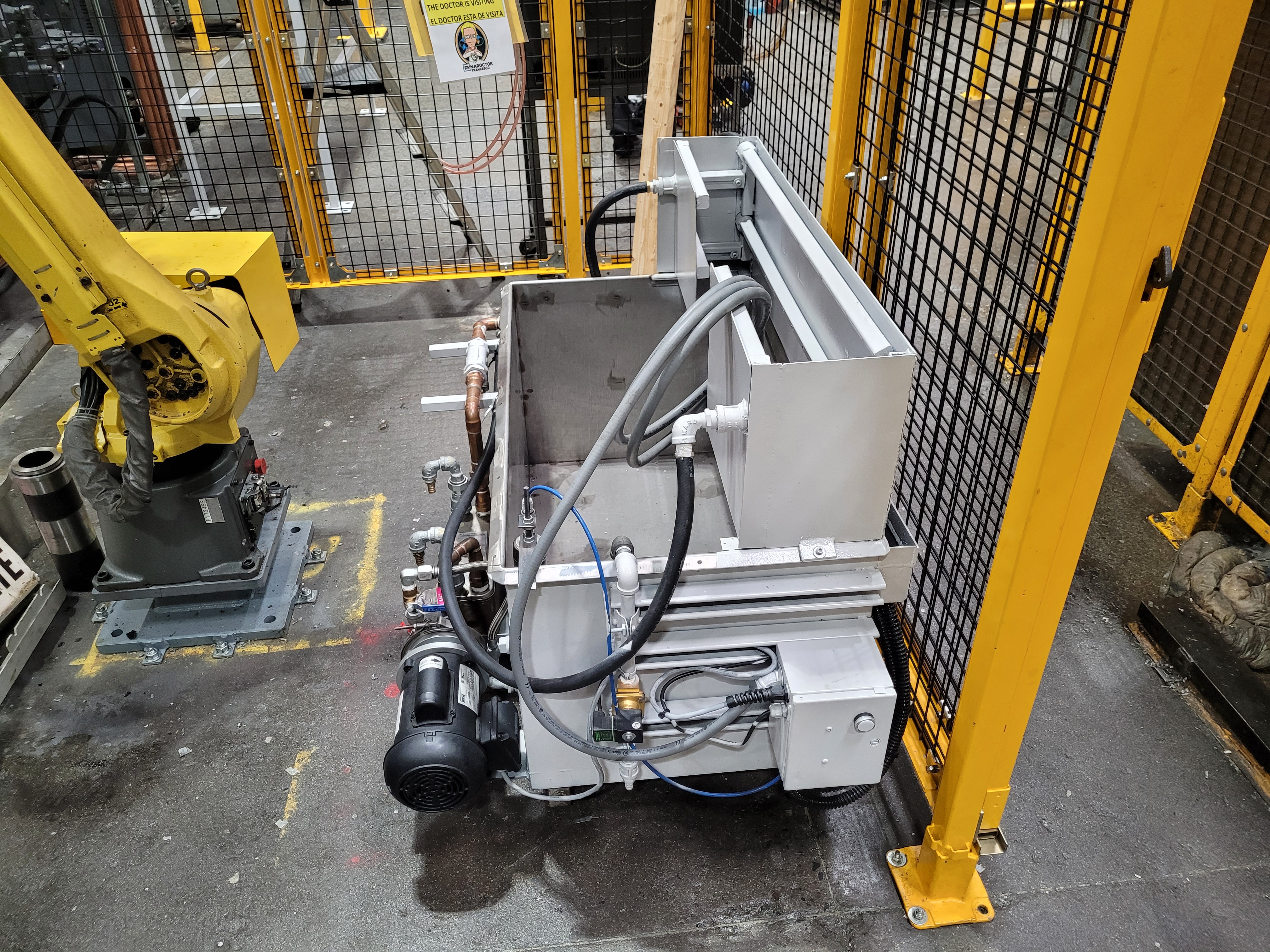
Die cast parts come out of the machine very hot, and are immediately quenched in oil or water solutions for case hardening purposes to increase part durability. With this in mind, Dynacast at Lake Forest had at some point in the past designed and built a self contained mobile quench tank with a built in air blast feature to remove leftover droplets from the quenching process before trimming the parts from the runner.
I was brought in to this project to make updates to the design and help guide the maintenance department as we struggled to design a tank that could be copied easily while maintaining built in features of the original like adjustable air shielding, all at a minimum cost.
Working with the maintenance department using scrap metal on hand and the skill of my welder Isauro, we were able to produce a quench tank that mimicked formal sheet metal fabrication techniques using pieces of flat stainless steel only, complete with adjustable air blast shielding and improved storage for secondary systems like the pump and filtration system.
Continuous Improvement Projects
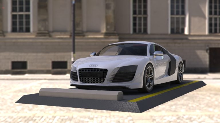
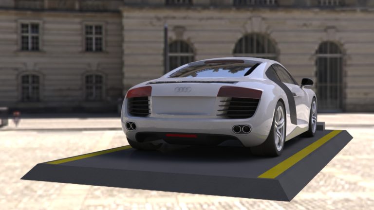
Audi R8 CAD model
As an engineer, I believe that it is my responsibility to always be continuously improving and developing my professional skill sets in order to help ensure that any project I am associated with is being delivered with the best possible quality. As part of this, I purchased and invested nearly 110 hours studying advanced complex surface modeling techniques in Solidworks by modeling the exterior paneling for an Audi R8. These methods were challenging to learn and apply, but ended up being very useful years later designing things like prosthetic housing that required fine tuned ergonomic profiles.
Roseville Precision Quality Department
While working in the sheet metal industry as a quality department lead, I was responsible for both dedicated and spot checking each step in the fabrication process for over 50 different operators. Catching easily missed errors such as parts bent inside out, inserts pressed in upside down, coating and paint application issues up to basic interpersonal miscommunication. My word was final on part production, and I prided myself on having only missed a few things during my tenure.
While working in the floor office, I implemented simple changes to the document control methodology such as a single check box step added to the traveler that ensured that the job tracking board was always synchronized with the jobs arriving in the shipping department. At one point after this change was implemented, a magnet on the job board was found that had not been moved into the final process column, so I went to investigate the order and I discovered that a critical final check had not been completed and would have been missed. This experience taught me about how even small process changes can do a lot to protect the shop from miscommunications.
As part of my personal philosophy of continuous improvement, I saw an opportunity to translate the knowledge I was teaching myself after hours into standard operating procedures for the machine operators on the factory floor. Many of these employees worked on the basis of tribal knowledge built primarily on the foundation of the person who had done their training. A portion of these employees did not understand the methods or reason behind why sheet metal fabrication was done in such a particular way, so I started to organize this information into an easily accessible set of training documents.
Although this was my first attempt at writing and implementing standardized procedures and the results did not turn out very well in this instance, the groundwork was laid for later projects that were more successful.
Dynacast improved conventional tool templates
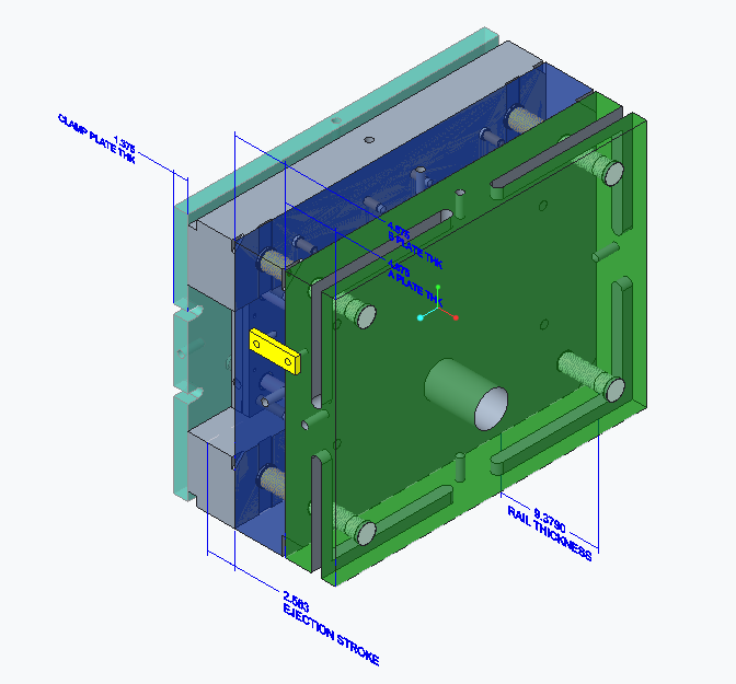
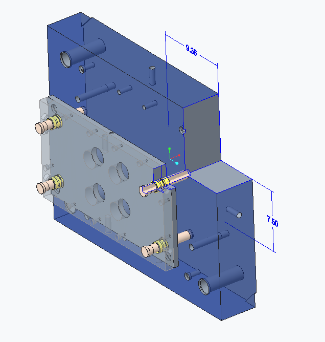
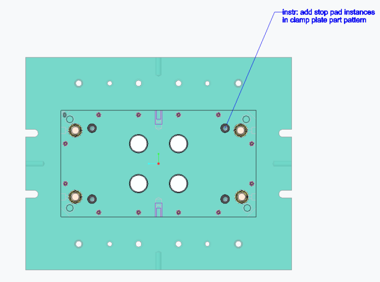
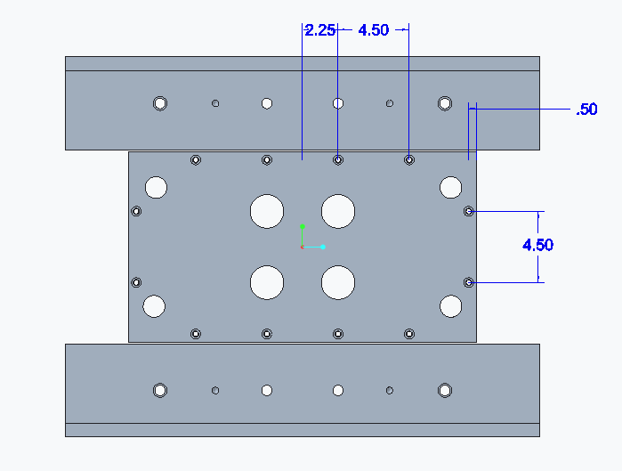
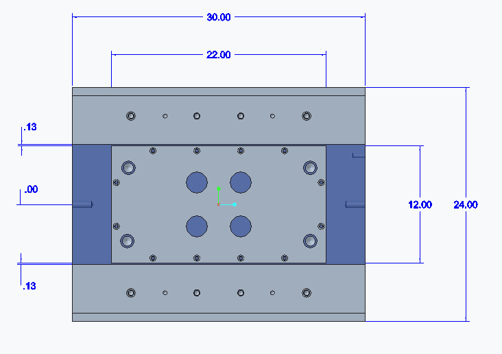
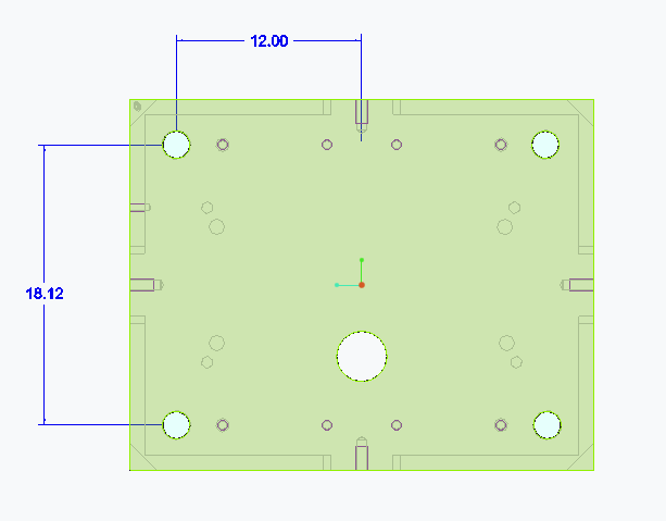
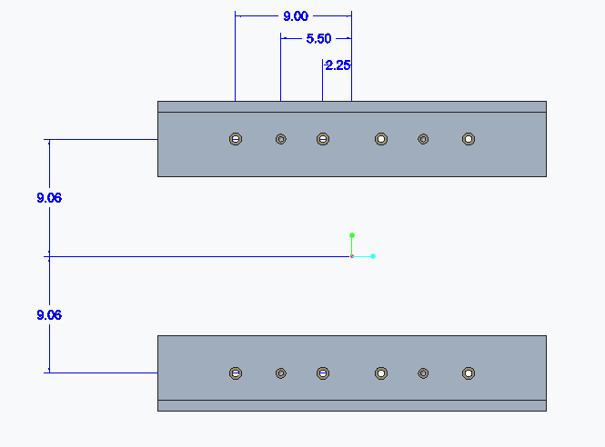
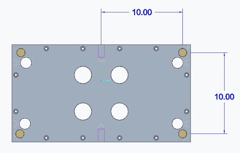
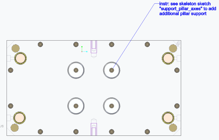
Working at the tooling design division for Dynacast was my first introduction to using a top down design methodology in Creo. For those unfamiliar with traditional design software packages, Creo (formerly PRO/E) has a notoriously difficult learning curve that can be challenging even to veteran designers. This is important to note because in just under one year of studying, I went from a brand new Creo user to designing next generation example tool templates. These new templates took advantage of advanced data structures like skeleton models, assembly relation coding, custom parameter scripts, and combination states highlighting critical control dimensions.
These improvements taken together created an easier workflow that new designers would be able to follow through quickly while avoiding simple mistakes. The images collected here show the different combination states that are all coming from the same tool, these states allow the designer to focus in on a subset of the die tool (e.g. isolating the ejection system), make appropriate dimensional changes that are automatically highlighted and presented to the designer and then return back to the full assembly while avoiding an over-reliance on tribal knowledge
Dynacast automated design checklists
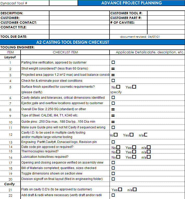
A major part of the Dynacast tool design process was filling out a specification worksheet in Excel as part of the release process for any new tool. This document, referred to as a design checklist, came in four versions each uniquely tuned to a specific type of tool that we manufactured. When I first arrived in Wisconsin, this meant that releasing a new tool required filling out this form by hand, which included lots of different information sections that may not be applicable on a tool by tool basis. In addition, the original form is somewhat hard to read, requiring tribal knowledge of the design and fabrication methods used at Dynacast, which only increases the operating difficulty for newer designers who do not have extensive access to this foundation of tribal knowledge.
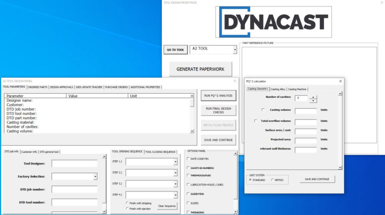
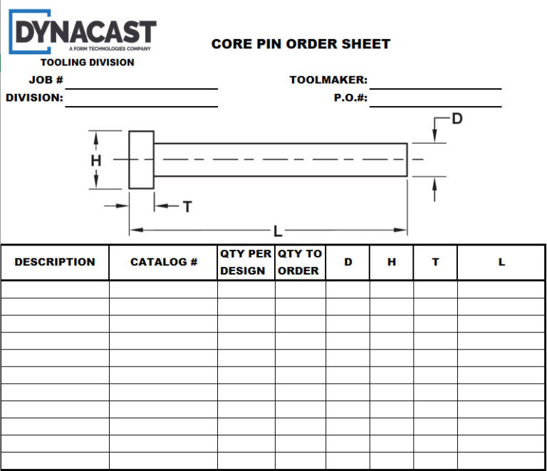
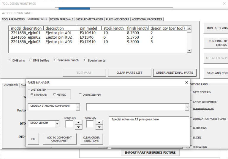
In response, I decided to teach myself how to write user forms in Excel using the visual basic language in order to create a single excel document that could manage all of these specifications while protecting designers from making simple mistakes and thus freeing them up to think about more important aspects of the design. This work later led to more advanced automation when I realized that excel could share data directly with the model and that Creo could act on this information. Instead of the designers having to comb through the model to fill out the paperwork, I could flip the script and have the paperwork directly control the model!
Taken together, these scripted tasks would have reduced the time needed to prepare a new tool design from nearly two weeks down to two days!
